FDM vs. DLP 3D Printing
Two common 3D printing processes are fused deposition modeling (FDM) and digital light processing (DLP). Each of these 3D printing processes is best suited to specific product applications. Anyone interested in using 3D printing for their next product should understand the differences between FDM vs. DLP 3D printing. DLP processes and systems enable the manufacturing of products like dental appliances, medical devices, and footwear. With greater speed, better surface finishing, and isotropic material properties DLP may be a better choice for companies looking to decrease product development time, de-risk manufacturing operations, and create unique business models.

Two common 3D printing processes are fused deposition modeling (FDM) and digital light processing (DLP). Each of these 3D printing processes is best suited to specific product applications. Anyone interested in using 3D printing for their next product should understand the differences between FDM vs. DLP 3D printing. DLP processes and systems enable the manufacturing of products like dental appliances, medical devices, and footwear. With greater speed, better surface finishing, and isotropic material properties DLP may be a better choice for companies looking to decrease product development time, de-risk manufacturing operations, and create unique business models.
FDM vs. DLP 3D Printing Processes
All 3D printing processes have similar characteristics that reduce manufacturing risk, eliminate tooling time and costs, enable manufacturing of new unique designs, and help companies remain agile. Companies need to carefully choose which processes and materials are best suited for their products to achieve optimal performance for their business requirements. FDM (also called fused-filament fabrication) and DLP (digital light processing) are two 3D printing technologies that enable an on-demand manufacturing model for many products.
Fused Deposition Modeling (FDM)
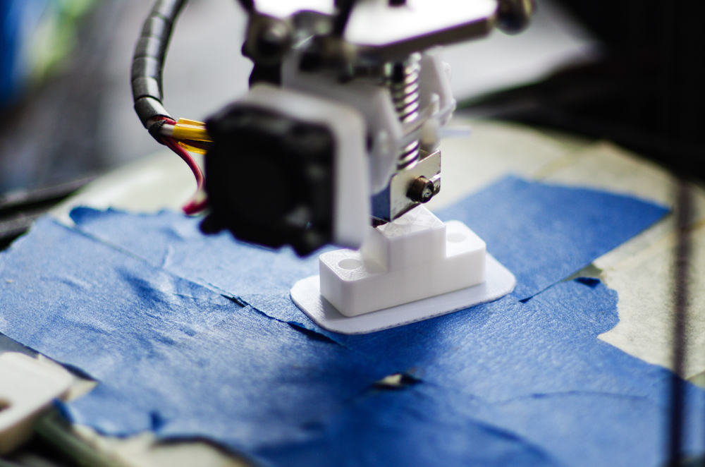
An FDM 3D printer operates by extruding a thermoplastic filament through an aperture while tracing a part’s structure on a horizontal platform. The printer head heats the filament, and the heated filament fuses back into a solid as its head traces and fills the cross-section line by line, then advances this process layer by layer. The market considers the FDM line-by-line tracing process to be the slowest, requiring significant post-processing to deliver the final product. However, large parts with complex structures can be built up from various filament materials, including fiber-filled and unfilled polymers, to produce plastic parts.

Digital Light Processing (DLP)
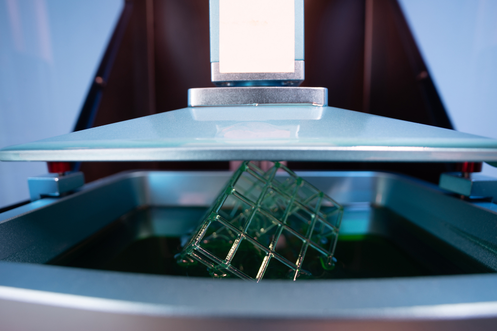
DLP is used to fabricate a product on a build platform on top of a vat of photosensitive resin. A cross-sectional image of a print layer is projected from a DLP chip onto the resin, causing the exposed resin to harden. Each layer is built up vertically as the platform slowly raises from the resin vat. All points in each layer cure simultaneously, making layer printing time much faster (minutes) versus FDM (hours), where each layer requires area tracing. As each layer hardens, the build platform moves to allow the resin to fill the next cross-sectional area with fresh resin ready to be cured. Once the part finishes printing, the part is removed, washed, and cured. DLP printing speed, surface finish, and dimensional accuracy are vital advantages over FDM.

Comparing FDM vs. DLP 3D Printing
In a direct comparison of FDM vs. DLP 3D printing processes, each process offers unique advantages in the following areas: resolution, build volume, printing speed, and post-processing steps:
| FDM | DLP | |
| Mechanical Properties | Has inferior mechanical properties in the z-direction requiring either specific orientation of parts during printing or larger and heavier parts to compensate for anisotropic material properties. | Achieves superior isotropic mechanical properties similar to injection molding with equivalent mechanical properties in x,y,z directions. |
| Resolution and Accuracy | FDM has lower accuracy depending on nozzle aperture size and printer design quality. Accuracy range: [+/- 200 micrometers]; Minimum layer thickness: 127 micrometers; Minimum suggested feature size: 1.15 mm. | It has the highest accuracy enabling very complex geometries. [XY resolution: 75 micrometers]; Layer thickness (Z resolution) from 20-150 micrometers; Minimum suggested feature size: 0.1 mm. |
| Build Volume | Support small and large build volumes (up to 1 m3) | New printer build volumes increase to larger form factors (up to 400 mm x 400 mm x 400 mm). |
| Surface Finish | It requires significant post-processing to smooth out layer lines and drill out support structures to achieve smooth hole features. It is limited to simplified models and geometries. | Achievable variety of surface textures. Requires less post-processing as there are limited or no layer lines. Able to print complex geometries. |
| Speed | Slow; large parts can take days to print. Batch printing time slows for full batches having to trace each part cross-section in series. A 190 x 120 x 380 solid box will print in 133 hours, up to .3 cm per hour on FDM printing. | Generally prints parts faster than FDM. Batch printing can apply to smaller parts. Each batch layer takes less than three seconds to complete. 190 x 120 x 380 solid box can print in as little as 2.5 hours. Advanced DLP systems can print up to 15 cm per hour. |
| Applications | Tooling and jigs, mechanical fixtures, rough prototypes. Applications that accommodate heavier parts and low flex and low z-properties. | High surface finish and accuracy, energy return and dental and medical products, footwear, lattice structures for variable stiffness, and light-weighting. Applications where the highest performance, lightweight, highly complex parts that require isotropic properties are needed. |
| Materials | Primary materials include thermoplastics with various properties from rubbery to rigid, including TPUs, ABS, and polycarbonate. | Thermoset plastics (plastics that can’t be melted again after forming) starting in a resin form. Materials have properties ranging from soft and rubbery to rigid. Chemistries of the plastics are tuned to meet the needs of the application. |
| Post-Processing Steps | FDM requires significant post-processing (i.e., support removal, tumbling, vapor smoothing, and machining) to remove support structure, achieve dimensional accuracy, and ensure surface finish comparable to DLP. | Requires wash and cure steps to achieve high-performance mechanical properties. Dimensional accuracy does not require machining. Requires minimal removal of support structures. |
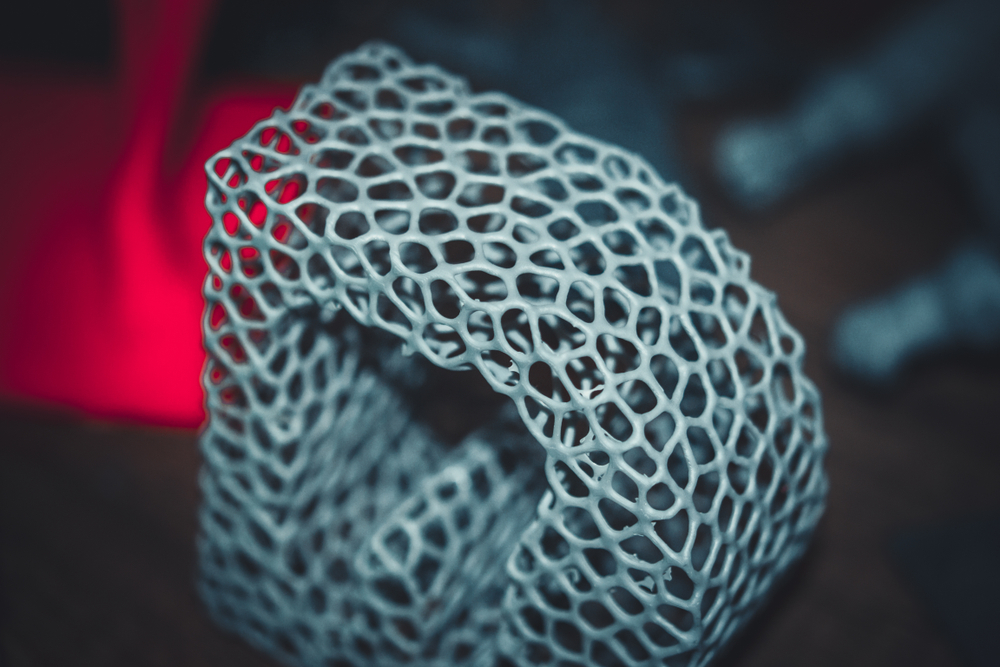
| Complex structures | FDM cannot produce fine features, such as those required for producing lattice structures (1.15 mm minimum feature size). | The minimum feature size for DLP printing allows for fine detail and complex structures. DLP printing is ideally suited for producing lattice structures. |
Best applications for DLP include products that require fast printing, high-performance, precision, and high-quality finishes, such as production parts, dental products, high accuracy tooling, and footwear. FDM is best applied to slow printing applications that include large, bulky products that do not require the highest precision and can accommodate inferior mechanical properties in the Z direction.
FDM vs. DLP 3D Printing Workflow
When considering FDM vs. DLP 3D printing workflow, it helps to compare the entire workflow from idea to produced part. This comprehensive workflow framework will help end-users decide which technology is best for their intended use.
The design process for FDM and DLP 3D printing is very similar. However, after converting the design to an STL file, the processes diverge. When preparing the STL for printing, several factors come into play, such as generating a support structure, speed of slicing, and manageability of print files. FDM vs. DLP 3D printing processes use similar pre-production workflow steps to prepare designs for printing. However, the similarity stops at that point.
DLP printing speed and reduced post-processing are key advantages over FDM. FDM has traditionally benefited in large printing volumes. However, this advantage shrinks as DLP build volumes have increased, and companies break products into smaller parts to access DLP speed, accuracy, and faster overall workflow.
CAD to STL: Equivalent Process Innovation
The CAD models are imported into 3D printing software in a 3D-printable file format (example: STL or OBJ) or converts after import. Material and printer are selected, and each model orientation is adjusted to maximize the number of parts per batch and minimize the size of any required support structures. The support structure can automatically generate, allowing for manual adjustment, and later are sliced into layers with printing parameters. For volume production, the operator may look to fine-tune parameters to improve yield and printing speed to maximize printer productivity and material utilization.
Printing Speed in FDM vs. DLP 3D Printing
A significant difference between FDM vs. DLP 3D printing is printing speed. Small parts, defined as a low percentage of the build volume ratio to the printing volume, will have a more similar print time in FMD and DLP printing. But, FDM cannot produce parts with the same surface finish and precision at small scales.
In contrast, large parts have different printing speeds in each process. FDM printing is slower with larger parts because the print head must travel and cover so much surface area. DLP printing uses a projector to cure an entire layer at once, giving faster printing speeds. FDM requires a separate material for support structures, while DLP uses the same material. Switching between support material and model material on each layer is time-consuming, even with multiple extruder heads on the printer, further slowing the printing process.
Post-processing in FDM vs. DLP 3D Printing
Finally, there is the need for post-processing. DLP does not leave large layer lines along the surface of the deposited structure. DLP-compatible materials require a resin removal step, and some materials may require post-curing and polymerization steps. In contrast, the FDM process leaves thick layer lines that require mechanical sanding and polishing.
Support removal in FDM printing comes in two forms: manual support removal and chemical support removal. Manual support removal requires a great deal of time and labor to remove even small amounts of support material. Chemical support removal leaves the part saturated in caustic chemicals to wash. While there is less labor time in the chemical support removal process, there is a significant time in dissolving the supports in a chemical bath, which can take up to four hours for large parts. DLP printing requires smaller support structures to support a part fully. A simple hand tool can clip support structures, or a tumbler can automatically break off the support material and polish the part.
In FDM printing, complex parts can have support structures that eliminate the possibility of manual support removal, leaving the operator dependent on chemical baths to remove all the support. DLP printing will often produce complex structures with no support material required, leaving a part with a much better surface finish.
Once an operator removes support material, they may need to polish the part. FDM printing requires a large amount of polishing to get the surface finish to the same point DLP printed parts come off the printer. Polishing includes a combination of manual sanding, tumbling, and vapor smoothing, all of which are time-consuming processes. DLP requires only simple buffing to remove support structure contact points.
Skilled operators will know the best combination of manual and automated solutions to give the best results. An experienced 3D printing partner can help companies determine the best course of action for scaling production with these 3D printing processes.
3D Printing Partners Can Help You Choose the Best Process
Companies considering using 3D printing may want support to determine the best 3D manufacturing process for their products. Companies need to consider whether to bring 3D printing capacity in-house or whether to outsource to a contract 3D printing service bureau. The best 3D printing manufacturing partner can help qualify designs, fine-tune printing processes for new or existing products.
Advanced service bureaus can now offer their clients access to cloud-connected 3D printers in an overseas or local smart factory, giving on-demand access to advanced 3D printing systems that use DLP 3D printing with photosensitive resin materials. A 3D printing partner with this kind of on-demand option de-risks a go-to-market strategy by providing flexible production capacity, low MOQ, and eliminates large quantities of held inventory. This on-demand production route is useful for prototyping, low-volume manufacturing, and full-scale production.
LuxCreo’s patented LEAP™ (Light Enabled Additive Production) process is the ideal 3D printing process to help you scale. We offer cloud-connected 3D printers, high-performance materials, and on-demand Smart Factory production service in rapid prototyping applications. For more information on how our services can improve your supply chain and manufacturing processes, visit our contact page or call (650) 336-0888.

